Adres
16100, 5.cd No: 13
Hasanağa Organize Sanayi Bölgesi, Nilüfer/Bursa
Çalışma Saatleri
Haftaiçi: 09:00 - 18:00
Adres
16100, 5.cd No: 13
Hasanağa Organize Sanayi Bölgesi, Nilüfer/Bursa
Çalışma Saatleri
Haftaiçi: 09:00 - 18:00
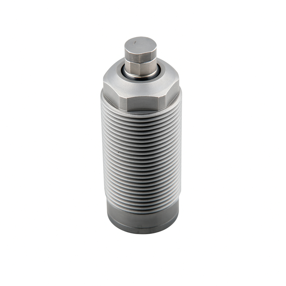
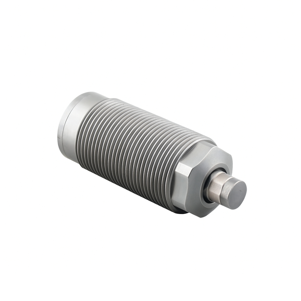
| Model | HWS-26AL-S | HWS-26BL-S | HWS-30AL-S | HWS-30BL-S | HWS-36AL-S | HWS-36BL-S | HWS-45AL-S | HWS-45BL-S |
|---|---|---|---|---|---|---|---|---|
| Operating Pressure Range (kgf/cm²) | 20 ~ 70 | |||||||
| Stroke (mm) | 5.5 | 5.5 | 8 | 8 | 10 | 10 | 10 | 10 |
| Piston Rod Diameter (mm) | Φ10 | Φ10 | Φ12 | Φ12 | Φ15 | Φ15 | Φ16 | Φ16 |
| Support Force (kgf)/Operating Pressure (kgf/cm²) | 170/50 | 170/50 | 220/50 | 220/50 | 330/50 | 330/50 | 530/50 | 530/50 |
| Operation Type | Single Acting | |||||||
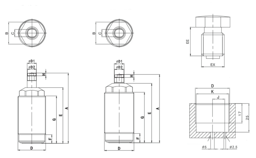
| Model | HWS-26AL-S | HWS-26BL-S | HWS-30AL-S | HWS-30BL-S | HWS-36AL-S | HWS-36BL-S | HWS-45AL-S | HWS-45BL-S |
|---|---|---|---|---|---|---|---|---|
| A | 72.5 | 66 | 81.7 | 73.7 | 77 | 69 | 92 | 82 |
| B | 22 | 22 | 24 | 24 | 30 | 30 | 36 | 36 |
| C | 9 | 9 | 10 | 10 | 11 | 11 | 14 | 14 |
| D | M26x1.5 | M26x1.5 | M30x1.5 | M30x1.5 | M36x1.5 | M36x1.5 | M45x1.5 | M45x1.5 |
| E | 57 | 57 | 62 | 62 | 58 | 58 | 71 | 71 |
| F | 8.5 | 8.5 | 9.5 | 9.5 | 10 | 10 | 9.5 | 9.5 |
| G | 49 | 49 | 54 | 54 | 48 | 48 | 60 | 60 |
| H | 3.5 | 3.5 | 4.5 | 4.5 | 4 | 4 | 4 | 4 |
| J | 9 | 9 | 11 | 11 | 13 | 13 | 16 | 16 |
| K | 24.5 | 24.5 | 28.5 | 28.5 | 34.5 | 34.5 | 43.5 | 43.5 |
| D1 | 10 | 10 | 12 | 12 | 15 | 15 | 16 | 16 |
| D2 | 9.5 | 9.5 | 11.5 | 11.5 | 12.5 | 12.5 | 15.5 | 15.5 |
| EE | 10 | 10 | 10 | 10 | 10 | 10 | 10 | 10 |
| EX | M8 | M8 | M8 | M8 | M10 | M10 | M10 | M10 |